Front and rear frame skirts |
 |
When describing the reaconstruction of the water tank I already noted that the front and rear frame skirts are an evident mismatch with the water tank's sides. Now that the water tanks have been soldered in place I reconsidered this conclusion. But no matter how I looked at it there was no way to make them fit, so I decided to discard the original parts and make two new ones myself. |
 |
First I had to fabricate a drawing of the skirts, so I turned to the computer. I used a frontal photo of the loco and cut out the skirt as an underlay. I then drew the appropriate lines and rivets. When done I scaled the completed drawing down.
I printed the drawings on photo paper and cut it out to see of it would fit accurately. Well the first attempt was a too small by a few tenths of a millimeter so I resized and reprinted the drawing. The second attempt was bulls eye! |
 |
I cut a piece of brass sheet approximately to size and soldered it onto the original sheet. This way I could make two identical skirt in one go.
I used 0.45 mm hard brass sheet. This is a bit thick but these skirts easily bump into something so I thought it would be better to make them a bit sturdy.
I attached one of the printed drawings to it with a few drops of ordinary household glue. |
 |
From there I could saw on the table saw the twin skirt almost to size |
 |
After a filing exercise they were a perfect fit. |
 |
I separated the two skirts and glued them on a aluminium angle. I also glued two new drawings on them. I drilled the rivet pattern. In advance I adjusted my drill stand so that the drill would not pierce through but would stop about 0.2 mm short of that.
I was very happy with my crosstable which made it easy to drill a quite regular pattern of rivets at a distance of 1.2 mm from each other.
Before drilling there is a good time to remember that you’re drilling in the backside of the skirts and that you should mirror the pattern. I forgot and one hole ended up on the wrong side of the loco. |
 |
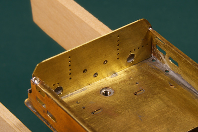
The upper skirt on the photo is the front skirt, with the two holes for the piston sleeves, the lower is the rear skirt with four holes to mark out the rectangular opening that must be sawed with a piercing saw. |

Ready. Holes for the couplers and buffers drilled, the rectangular holes sawed and filed and the rivets pressed out. I am not entirely happy with the rivets, they are not very crisp, but it will do.
|
 |
Trial fitting one more time, fire up the soldering iron. |
 |
Tack soldered in place. Once all adjustments had been made, I ran a fillet along the length |
 |
 |
 |
A separate sheet was made to fit over the piston sleeves,
0.2 mm thick. |
 |
This sheet apparently closes a corresponding gap in the front that is visible on the rear. |
| |
|
 |
I added a thin sheet of brass behind the steps that still needed to be closed and filled the offending holes with solder and filed them flush. |
 |
The remainder of the hole was filled with Milliput and sanded flush |
| |
|
 |
There was also a minor issue with the buffers. They were of the open type, with the springs showing. The prototype is open to the top and bottom side. The buffers in the kit were open to four sides. |
 |
I closed two opposite sides with Milliput and sanded them. |
| |
|
| |
|
| |
|
| |
|


Sign my
GuestBook